Archive for the ‘Framebuilding’ Category.

Travel Gifford

On my last blog post I mentioned a secret project.  I built an adventure touring bike (basically the same geometry as Gifford) that uses S&S couplers to make travel easier while waiting for the dropouts to arrive for my other frame project.  I’m really happy with how this one came out, especially since I started it only 4 weeks ago.  This also makes it the first complete bicycle to come off of my new frame fixture.

As I mentioned it is very similar to Gifford.  The head tube angle is 73 degrees and the seat tube angle is 72.5 degrees.  It is built for 26″ (559mm) wheels because they pack a bit more easily into S&S cases and it will be easier to find replacement tires in foreign countries.  There is tons of tire clearance, the photos here show it with 50mm knobby tires and fenders will fit above those.  I’ll probably run it with 45mm or so slicks most of the time.  The 60mm knobby tires from my mountain bike even fit.

The frame is a bit larger than the other Gifford to make it on the slightly large size for me and to make it fit many of my taller friends who might use this as a loaner bike.  Sizing is about the same as a 60cm Long Haul Trucker.  This one is also built with derailleurs instead of a Rohloff hub to keep costs down.  Tubing is similar to the first Gifford, Columbus SL (standard diameter 9/6/9) front triangle, the same Nova single bend chainstays, and some True Temper oversized seatstays that looked good to my eye.

It will eventually get a coupled porteur rack to go along with it.  It is shown here only partially assembled because my friend Andre is going to do the rest of the assembly and give it a test ride.  He is interested in this style of bike and is waiting for the next batch of Rawlands rSogn frames to be made.  In the meantime he’ll get to use this one for a few months.

Lots of tire clearance up front under the Pacenti Biplane crown

Lots of tire clearance in back too. The oversized double taper seatstays will make the braking firm.

The seatstay cluster is fairly plain, but gets the job done. This is the trickiest part of the bike for me to get right.

Single bend chainstays clear 48/38/24 chainrings (barely) and provide good tire clearance.

There are more photos on my smugmug site.

I’m going to be asked how I got the S&S couplers.  These were removed from a damaged frame  but where the couplers were intact.  I cleaned them up carefully and reused them.  It would be nice if S&S sold them to hobbyists, but I understand why they don’t.  I really enjoyed working with the couplers, they must be the most precise lugs ever made.  The fit was perfect and they have very nicely tapered edges.  I inserted the couplers into my downtube and toptube before they were brazed into the frame, but after the tubes were mitered and fit to my jig.  That method seemed to work nicely for me, and the couplers have perfect alignment.

I’m really excited to get this one on the road.  I have a bit of travel coming up soon and may bring the bike with me, even though I hadn’t really planned on bringing a bike.  In the meantime I look forward to hearing what Andre has to say about the ride.
Snow Day

It’s been quite on the blog since I’ve been busy working away on a top secret project and traveling for work.  The blog should pick up soon.

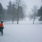
Today Seattle has a few inches of snow.  The last time that we had snow like this was Christmas 2009.  I woke up early and enjoyed a nice ride in the stuff with Rory.  I’m glad to get to ride it in once in a while, but I’m happy not to have to commute in it on a daily basis.

Secret project hint: It is a variation on Gifford, my adventure touring bike.  Here is a teaser (that is a 48mm wide tire):

Seat tube angle adjustment on the frame fixture

There was some confusion on the framebuilder’s list on how the virtual pivot point works on my frame fixture (and on the Arctos).  I took some more photos to try and explain how it all works.

Here are some photos showing how the parts fit together:

This is the seat tube angle adjustment backplate. The adjustment plate rides in the groove slot on some brass pins. There are some machining errors visible in this view, but they don't affect the precision.

This is the back of the adjustment plate. The groove in it is for the locking handle to pass through.

The adjustment plate is mounted on the backplate.

This video shows it all in action.

Click this photo to see a video that shows it all in action. Watch how the BB position doesn't change.

My new frame fixture

I started on this fixture a couple of months ago, then back burnered it.  A couple of weeks ago I started to get active again and this weekend I was able to put the finishing touches on it.  I’m really excited about how it’s come out. 

It is highly insipired by the Arctos Frame Jig that was designed by Gary Helfrich.  The details and implementation are different, but it is setup in the same way and I copied the basic overall shape and virtual BB pivot of the Arctos.  I always liked the idea of the Arctos Frame Jig because it was made of T-Slot extrusion (in my case I’m using 15-series 8020).  That makes the fixture a bit more modular (so that I can reconfigure it for different needs) and kept the largest pieces that I needed to machine relatively small.  It doesn’t make it easier or cheaper to make the fixture compared to other designs, there are still over a dozen custom cut parts on here which required high precision and 8020 extrusion is not cheap.

A key feature of this fixture is that every adjustment is locked independently.  My old fixture had many parameters locked with the same few bolts.  With the old one if I screwed up a miter and made a tube 1mm too short I’d spend 20 minutes rejiggering everything and getting it all aligned again.  On the new fixture I’d just need to unlock a couple of handles, slide one part to make the small adjustment, and lock them again. 

It was really important to me to have a fixture that makes it easy to install and remove the frame. This fixture makes it easy, you just raise the upper head tube and seat tube cones, release the dummy axle using the quick release, and remove the shaft collar that holds the bottom bracket in place. Many other designs have solid rods which run through the head tube and use many more clamps around frame tubing, but I didn’t want mess with all of that.

This new fixture is much easier to configure than my old one.  The basic measurements required are:

  • X and Y from the center of the bottom bracket to the bottom of the head tube (438mm Y, 451.7mm X in the drawing below)
  • Head tube angle
  • Seat tube angle
  • Bottom bracket drop
  • Chainstay length
  • Head tube length
  • Seat tube length

Here is a drawing for the next frame that I’m building which shows these dimensions (in red).  It also lists dimensions for mitering (in cyan).  That is basically everything that I need to make the frame.  This bike will be my new commuter, replacing my Novara Fusion.

The fixture will have scales which allow for direct reading of the first 4 items listed.  Currently there isn’t a permanent scale for the X offset, but I have a simple solution of clamping a ruler in place.  I did make direct reading scales for the head tube angle and seat tube angle, shown here:


The bottom bracket drop also is set from an easy to read scale.  The alignment of the bottom of the dummy axle with the scale shows you the bottom bracket drop (74mm in this example):

It isn’t obvious from photos, but a tricky part of the Arctos Jig (and this one) is that the BB position stays static as you adjust the seat tube angle.  The same is true for the bottom of the head tube.  The seat tube angle adjustment has a virtual pivot point around the bottom bracket despite not having anything connected to that pivot point.  That is done with two slots that are concentric around the bottom bracket.  I cut these on my baby sized CNC mill, this would be a much harder operation to do on a manual machine.  The HTA block has a real pivot which is aligned to be directly under the bottom of the head tube.


The rear triangle setup is pretty easy.  There is a rear triangle tower that has a quick release dummy axle holder that is centered with respect to the tube cones.  It can be slid back and forth by opening two handles, and then you can read the rear chainstay length using a ruler:

Arctos Jigs use solid aluminum for the standoffs to this rear tower.  I hate drilling really deep holes in solid aluminum, so I used 80/20 which already has a hollow cavity down the middle.  The end plates that I made keep the threaded shaft for the locking T-Nuts in place:

I used the bottom bracket post from my old jig, but I’ve always been proud of this design.  The key is using an adjustable locking shaft collar (about $30 from McMaster Carr).  That shaft collar gives me a fine adjustment for the offset so that I can handle 68mm to 73mm bottom brackets easily.  Removing the outer locking shaft collar frees up the frame.  The rod running through the bottom bracket is solid 5/8″ steel and is plenty beefy. 

I’ve already been asked if I’m going to make this fixture as a kit.  The simple answer is no for two good reasons:

  1. It isn’t my design.  I wouldn’t feel comfortable selling anything that was so heavily copied from an existing source.
  2. There are a lot of parts in this fixture that were done on my manual mill and which require a good precision.  I think that a realistic estimate would be 15-20 hours of labor per fixture.  I just don’t have that amount of free time and would rather use what I have to build frames, spend time with my family and friends, ride my bike, etc.

However I am helping Alistair Spence make one of these fixtures for his shop.  I’m excited about the possiblities of us both having compatible fixtures, it opens up options to make unusual hybrids for building tandems or cargo bikes somewhere down the line.

I’m writing this post while on limited sleep, so hopefully it makes at least a little sense.  If you have questions leave comments here, on my smugmug (permanent), or my flickr (free account, so photos will fall off over time).  There are more photos published in both locations than in this blog entry, and you can find high resolution versions of all photos there.

Disk Fork for my Porteur

As I mentioned in a recent blog post I’m building a new commuter frame and fork.  I’ll be moving all of the parts over from a Novara Fusion that I bought.  That includes the disk brakes.

I don’t like most disk brake rigid forks because they are either straight blades or have a really ugly bend to them.  I wanted to build something that looked a bit more traditional.  This presents an interesting design challenge though, since disk brakes are known to “unrake” forks with a tight bend.  My solution was to make some custom dropouts that extend far above the disk caliper into the more stout portion of the fork.  The dropouts had the match the bend on the fork blades.  I still consider this an experiment until I’ve put some hard riding on the fork.

I love the results!   It still isn’t as elegant as a nice flat crowned fork with a brazed on centerpull, but it doesn’t look half bad.

The brazeon count is a bit out of control.  There are eyelets near the bend for fender mounts, eyelets at the midfork and embedded into the crown for mounting a porteur rack, and a simple cable guide for keeping the brake cable out of the way. 

I did use a trick.  The brake is a “rear” disk brake because those are mounted inline with the dropout.  “Front” ISO disk brakes are offset by 4mm from the dropout, and that wouldn’t have allowed me to make one piece for both the dropout and the disk mount.  I wanted a single piece because it saved me from making a fixture for the disk brake mount or making a really complicated dropout.

NOTE: This trick doesn’t work. Read the comments for more details. I got away with it with a BB7 that is highly adjustable, but don’t think it will work with other disk brakes.

The dropout has Keith Anderson TITO stainless inserts brazed in.

Next up: finish up the new frame jig and build the frame.  A rack might come out around the same time.

Fork Fixtures are available

I spent a rainy Saturday finishing up 6 fork fixture kits.  The 5 prototypes that I made have been in use for about 6 months now and everyone who has reported back has been very happy with the kit.  The fork jig is designed to be fast to setup, accurate, and to provide a lot of brazing access.

For $90+$10 shipping you get this:

With the assembly instructions, around $100 in other parts, and an hour of time you can turn it into this:

 This is probably the only batch of kits that I’ll have available for a while, I want to make progress on some of my other projects. Email me (alex at phred dot org) if you’d like one and I’ll send you an invoice via PayPal.  Seattle residents can pick them up in person and save $10.

Sorry, I’m not shipping internationally right now.  I will start that back up in the spring.

A New Bike and My Next Project

A couple of months ago I bought a 2009 Novara Fusion bikes on closeout from REI:

The REIs around Seattle had a small number of these for half of their original price.  The bike came with front and rear Alfine hubs, generator lighting, fenders, a rear rack (that I removed), a chainguard, and disk brakes.  Not bad for under $500!

There are some nice details.  This taillight is battery powered and turns on automatically turns on if the bike is moving and it is dark out.  Sadly it uses a non-standard N battery, otherwise it is nicer (in brightness and function) than the Planet Bike Fenderbot.

There is a cool bell that is built into the brake lever that I’ll have to take a photo of later.

The disk caliper is tucked away on the chainstay, out of the way of the seatstay and rack and fender mounting.  The dropout even has provisions for the included kickstand:

I did replace a few components.  The stock cranks were wide and not very nice, so I put on something better.  I also replaced the tires, pedals, handlebars, and grips.

My next project is to replace the fork and frame with ones that I build.  The Novara frame has a reasonable geometry and fits me alright, but I don’t like the very stiff aluminum.  The fork needs more rake if it is going to work well with a porteur rack.

Tubing arrived for the new frame this week.  I’m using Pacenti Slant Six lugs with True Temper Verus HT 8/5/8 oversized tubing.  The lugs will keep the sloping top tube of the Novara, a feature that I like because it makes it a bit easier to loan the bike to friends who are shorter than me.  I don’t like the chain tensioner that came with the Novara, so I’m going to switch to the Engin/Paragon Rocker dropouts which have chain tensioning built in:

I think I’ll make my own front dropout that incorporates the disk mount and which extends high up the fork blade.

I’ve also been riding my last project all summer, but haven’t posted a photo of it since having it powder coated.  I still don’t consider the bike done because I haven’t built the light weight rear wheel or had the stem and rack chromed.  I’ve still put over 1000 miles on the bike in this unfinished state, so I maybe I should call it finished.

I love this bike.  It is fast, light, handles well, and looks nice.

Ivy-T stem

This is the first stem that I’ve built.  I did this one jigless, just counting on accurate miters to hold everything in place.  That worked pretty well, except that my front clamp was about 1mm off center (fixed that with a file, but that made it slightly narrower than I wanted.

Some details:

  • 1″ x 0.058″ extension (9cm long), 1.125″ x 0.058″ spacer, 1.125 x 0.051″ clamp.  I’d prefer to have more material on the clamp in the future, and may buy some thick wall 1.25″ stock to turn down.
  • roughly 95 degree angle (not measured precisely because it doesn’t really matter)
  • roughly 9cm long (same reason)
  • integrated cable hanger and spacers
  • non-stainless bolts for strength
  • the cable hanger fully pierces the top and bottom of the stem

double miter for the clamp and front

Checking the miters. Not done yet, there is too much of a gap under the handlebar clamp.

Brazed up. No burnt flux here!

I haven’t fillet brazed in quite a while, and was very happy with how these joints came out.   They didn’t require too much cleanup.

Ivy-T progress


The most important bit of progress is that the bike is rideable, and I’ve been commuting on it for a week.  It isn’t done, it needs a front rack, stem, and tail light (all will be custom), but rideable is a huge step.

It is a nice compliment to Gifford, pretty much the only bike that I’ve been riding for a year.  Gifford is utilitarian, the station wagon of a bicycle fleet.  The Ivy-T is much sportier, currently weighing in around 23# with fenders, battery powered lights, and a frame fit pump.  If I can keep it near 23# with generator lighting and the front rack I’ll be very happy.

Ivy-T in rideable, but not yet finished, form

The Diacompe GC450 centerpull brakes work very well. They almost never squeal, do a fine job of stopping, and are light and nice looking. I'm surprised, but the 27 year old brake pads (never used) even work well.

Brandon Ives did a nice job brazing the lugs (with silver). My fork crown, done in brass, is a little messier.

Here are some photos showing some of the fork building steps.  I don’t have a photograph of the fork raking because I raked these fork blades months ago at Alistair Spence’s shop.  I don’t have a fork bending form yet.

First the crown was brazed to the steerer. This is done first so that I can turn the crown race down on my lathe (easier without the fork legs attached).

I remove the flux and clean up the crown by hand. The aluminum rod sticking out is a part of the fender mount, and works with an eye bolt to keep the fender in place. It will be cut trim at installation time.

Dropouts are brazed in and cleaned up. I made these dropouts myself on the CNC mill.

I use this fixture to check the frame angles and set the fork blade length. The fork blades are uncut and the front axle height is setup until the angles are correct. The difference between the front and rear axle height (142mm front, 150mm rear) tells me how much fork blade to remove (8mm in this case).

The fork blades are not yet brazed during this operation. A dummy headset (made by Alistair Spence) is in place.

seat tube angle

head tube angle

The fork and trimmed down blades are set into the fork fixture for brazing. This is my second generation fork fixture, I'm going to sell these as a kit later this winter.

The blades are brazed into the fork crown.

The flux is soaked off in hot water and everything is cleaned up. The top hole on the inside of the fork crown is open as a vent hole and will be used to run the wire for the front light.

The fork alignment is checked on my alignment table. I had to tweak one fork blade slightly. Rake was left at 63mm.

Finally, here is a photo of the fender mount in use.  I learned about this setup from Jan Heine.  The fork crown is drilled in the back, and there is a blind hole in the front.   A piece of aluminum rod (fender stay) is put into place.  The tension of the fender’s eyebolt holds it in place.  It looks very clean, it is light, and it was easier than making a threaded fitting in the bottom of the fork crown.

Starting on the Ivy-T

Seattle’s rainy fall started today, which can only mean one thing: time for me to build a bike.  In the last year I’ve ridden all but about 200 miles on my new bike Gifford.  I like having a slim stable, but I also kind of miss having a second bike.

A few months ago I posted about getting this frame from Brandon Ives of IvyCycles.  The frame came to me with most of the hard work done (the front and rear triangles were done) and ready for all of the detail work.  I love the detail work, so this is a great partnership.  The brazing that he did looks great, hopefully I can keep a high standard on my part of the bike.

I call this bike the Ivy-T because it is heavily inspired by one of my favorite mass produced bikes, the Bridgestone RB-T, but built by IvyCycles.  The frame geometry is more or less a copy, just resized slightly to fit me better.  We used lighter tubing and better lugs that the original, but it is still Ishiwata tubing (this bike has 019 (8/5/8), the original used 022 (9/6/9)).  I still need to build the fork, but the bike will get a low trail fork that looks similar to the ones on my other bikes.  I’m going to use this fork crown:

Mitsugi Crown from Kirk Pacenti (bikelugs.com). The link takes you to the stainless version, but I'm using the normal steel one.

In the spring I was lucky enough to find a set of Dia Compe Grand Compe 450 centerpull brakes.  They came complete with braze-on studs, and had never been installed!  I’d been wanting a set of these brakes since first seeing them on a bike that Mitch Pryor (MAP Bicycles) brought to the 2009 Oregon Handmade Bicycle Show.  Centerpulls never really got my attention before, but I love the way these look.  They are a nice mix of refined and mechanical at the same time.  I watched eBay for a while and never saw any go by, but then these ones showed up on the BOB list.  I jumped on them.  Mitch was very helpful and emailed me original documentation for these which showed where the studs should be installed (the critical dimension is 62mm between the studs, although anything between 62mm and 65mm looks good to me).

Over the last week I made some curved bridges for the frame and brazed on the studs for the rear brake.  Here is are the photos from that process. 

I made this 3" radius bender using a circle cutting jig for the router and some scrap plywood. It was made in two halves with a chamfering bit.

This is what the bender looks like when assembled. To use it I just clamped it into my vise, trapping the end of my 3/8" tubing underneath. I pulled the other part around by hand.

I made this simple jig for holding the studs in place. I took this photo after tacking the studs, I wanted to check alignment before finishing the brazing.

I took this photo just after putting the torch down, but before removing the flux.

The flux has been soaked off. I'm pretty happy with how this brazing looks, I'm really out of practice. You can also see the curved bridge here.

Tons of clearance under these very pretty brakes. They are listed as 55mm reach, but I've never seen a 57mm reach dual pivot with this kind of clearance. The curved bridge hides nicely behind the brake arches.

I was really worried about having the gap between the brake arms be consistent and small. A little misalignment of the studs is barely noticable with cantilevers, but could cause big problems or look terrible with a centerpull.

One final shot of the installation, where you can see how the springs work.

Before installing the bridges I indented the chainstays slightly for increased tire clearance.  I hadn’t planned on doing this originally, but the brakes fit larger tires than I expected (my 38mm wide studded tires fit), and the chainstays were the limiting factor on tire clearance.  These photos are for JimG, who has asked me in the past for photos of my chainstay indenter.

I intend the chainstays on my 3" vise. Sometimes a skinny vise is useful!

Post indention, before bridge installation.

This is what the indenting form looks like. I made it from 5/8" rod, filled down to a reasonably nice shape, and brazed to a small piece of angle iron.